1.3. Message Switch Configuration Example
The Message Switch connects data streams between (and among) ICP devices, somewhat like an old-fashioned plug-in telephone switchboard. Figure 1-2 shows an example Freeway configured with four ICP devices:
-
Two WAN ICP boards (icp0 and icp1)
-
Two ICP_IP pseudo-devices (icp2 and icp3)
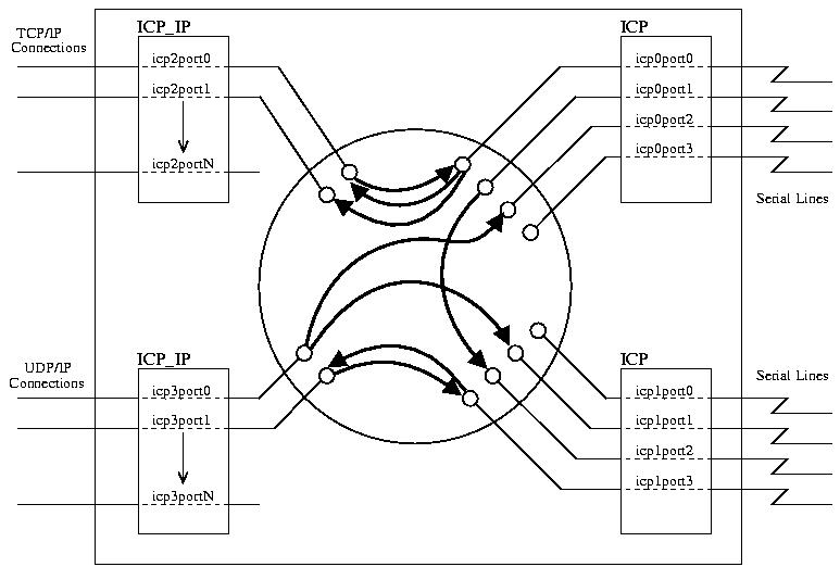
The Message Switch is shown as a set of arrows in the center of the circle. These arrows represent the switching paths of various data streams (icp0port0 to icp2port0, for example).
The Freeway and the Message Switch use several configuration files to specify the setup of various aspects of the system. These configuration files are described in more detail in Section 2.2. In the example system shown in Figure 1-2 the configuration is as follows:
- bootcfg
-
This Freeway boot configuration file specifies the number, type, and characteristics of all ICP devices. Note that the term "ICP devices" includes both physical ICP boards (which communicate via WAN links) and ICP_IP devices (which communicate via TCP/IP or UDP/IP, on an IP connection such as an Ethernet). In Figure 1-2, the bootcfg file has specified four ICP devices.
- muxcfg , swtcfg
-
These two Transport Subsystem Interface (TSI) configuration files specify the transport layer between the Message Switch and the Freeway. In Figure 1-2 these two files have specified a shared-memory transport (just as the Simpact-supplied files muxcfg.sra and swtcfg do; most configurations of the Message Switch should be able to use these supplied files without modifications).
- swdcfg
-
This DLI configuration file specifies the characteristics of each individual data link (baud rate, clock source, etc.). In Figure 1-2 the swdcfg file has defined 12 data links: icp0port0 through icp3port1.
- switch.cfg
-
This main message switch configuration file specifies the inter- connections between/among data links. In Figure 1-2, the switch.cfg file has defined 8 connections, each depicted as an arrow from one data link to another.
In summary, the bootcfg file defines the ICP devices, the muxcfg and swtcfg files define the transport layer between the Message Switch and Freeway, the swdcfg file defines the characteristics of each data link, and the switch.cfg file defines the interconnections between data links.